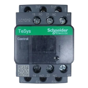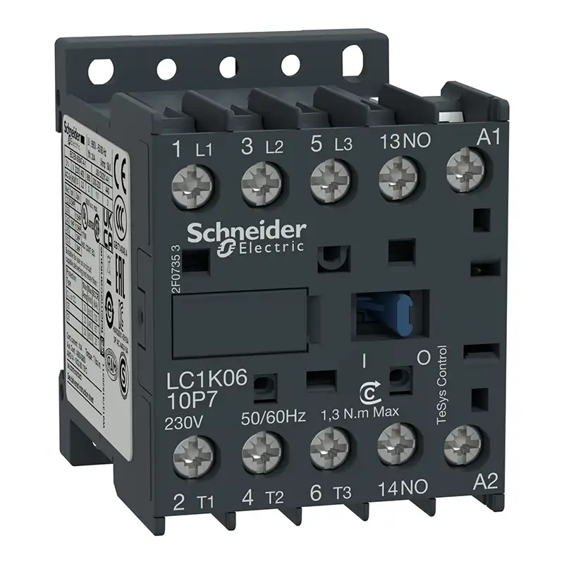
Schneider Electric 25A Contactor LC1K09 10P7
TeSys K contactor, 3 poles (3NO), for motor control applications up to 9A/690V AC-3 (4kW@400V), and for non-inductive load control applications up to 20A/690V AC-1. It provides a 230V 50/60Hz AC coil, 1NO built-in auxiliary contact, connection by screw clamp terminals. For operating rates until 600 cycles/hour and environments until 50°C, it procures reliability and durability to standard applications. Very compact (45mm width), DIN-rail mounting or screw fixing. Multi standards certified (IEC, UL, CSA, CCC, EAC), Green Premium compliant (RoHS/REACh).
- Delivering: We offer Nationwide Delivery - Monday - Saturday
- Call: +2348063316412
- Customer Care: We offer technical support and after sales service
- Address: Shop F464 F-Line Industrial Section, Alaba International Market, Ojo, Lagos State, Nigeria.
Description
Schneider Electric 25A Contactor LC1K09 10P7 230V 50/60Hz
LC1K0910P7, TeSys K contactor, 3 pole, AC-3 <= 440 V 9 A, 1 NO auxiliary, 230 VAC coil
TeSys K contactor, 3 poles (3NO), for motor control applications up to 9A/690V AC-3 (4kW@400V), and for non-inductive load control applications up to 20A/690V AC-1. It provides a 230V 50/60Hz AC coil, 1NO built-in auxiliary contact, connection by screw clamp terminals. For operating rates until 600 cycles/hour and environments until 50°C, it procures reliability and durability to standard applications. Very compact (45mm width), DIN-rail mounting or screw fixing. Multi standards certified (IEC, UL, CSA, CCC, EAC), Green Premium compliant (RoHS/REACh).
Specifications
| Range | TeSys |
|---|---|
| Product or component type | Contactor |
| Device application | Control |
| contactor application | Resistive load Motor control |
| Utilisation category | AC-3 AC-3e AC-1 AC-4 |
|---|---|
| poles description | 3P |
| power pole contact composition | 3 NO |
| [Ue] rated operational voltage | Power circuit: <= 690 V AC <= 400 Hz Signalling circuit: <= 690 V AC <= 400 Hz |
| [Ie] rated operational current | 9 A (at <60 °C) at <= 440 V AC AC-3 for power circuit 9 A (at <60 °C) at <= 440 V AC AC-3e for power circuit 20 A (at <60 °C) at <= 690 V AC AC-1 for power circuit |
| Control circuit type | AC at 50/60 Hz |
| [Uc] control circuit voltage | 230 V AC 50/60 Hz |
| Motor power kW | 2.2 kW at 220…230 V AC 50/60 Hz AC-3 4 kW at 380…415 V AC 50/60 Hz AC-3 4 kW at 440/690 V AC 50/60 Hz AC-3 2.2 kW at 220…230 V AC 50/60 Hz AC-3e 4 kW at 380…415 V AC 50/60 Hz AC-3e 4 kW at 440/690 V AC 50/60 Hz AC-3e 2.2 kW at 220…230 V AC 50/60 Hz AC-4 4 kW at 380…415 V AC 50/60 Hz AC-4 4 kW at 440/690 V AC 50/60 Hz AC-4 |
| Auxiliary contact composition | 1 NO |
| [Uimp] rated impulse withstand voltage | 8 kV |
| Overvoltage category | III |
| [Ith] conventional free air thermal current | 20 A (at 60 °C) for power circuit 10 A (at 50 °C) for signalling circuit |
| Irms rated making capacity | 110 A AC for power circuit conforming to IEC 60947 110 A AC for signalling circuit conforming to IEC 60947 |
| Rated breaking capacity | 110 A at 220…230 V conforming to IEC 60947 110 A at 380…400 V conforming to IEC 60947 110 A at 415 V conforming to IEC 60947 110 A at 440 V conforming to IEC 60947 80 A at 500 V conforming to IEC 60947 70 A at 660…690 V conforming to IEC 60947 |
| [Icw] rated short-time withstand current | 90 A 50 °C – 1 s for power circuit 85 A 50 °C – 5 s for power circuit 80 A 50 °C – 10 s for power circuit 60 A 50 °C – 30 s for power circuit 45 A 50 °C – 1 min for power circuit 40 A 50 °C – 3 min for power circuit 20 A 50 °C – >= 15 min for power circuit 80 A – 1 s for signalling circuit 90 A – 500 ms for signalling circuit 110 A – 100 ms for signalling circuit |
| Associated fuse rating | 25 A gG at <= 440 V for power circuit 25 A aM for power circuit 10 A gG for signalling circuit conforming to IEC 60947 10 A gG for signalling circuit conforming to VDE 0660 |
| Average impedance | 3 mOhm – Ith 20 A 50 Hz for power circuit |
| Insulation resistance | > 10 MOhm for signalling circuit |
| Inrush power in VA | 30 VA (at 20 °C) |
| Hold-in power consumption in VA | 4.5 VA (at 20 °C) |
| Heat dissipation | 1.3 W |
| Control circuit voltage limits | Operational: 0.8…1.15 Uc (at <50 °C) Drop-out: >= 0.20 Uc (at <50 °C) |
| Connections – terminals | Screw clamp terminals 1 cable(s) 1.5…4 mm²solid Screw clamp terminals 1 cable(s) 0.75…4 mm²flexible without cable end Screw clamp terminals 1 cable(s) 0.34…2.5 mm²flexible with cable end Screw clamp terminals 2 cable(s) 1.5…4 mm²solid Screw clamp terminals 2 cable(s) 0.75…4 mm²flexible without cable end Screw clamp terminals 2 cable(s) 0.34…1.5 mm²flexible with cable end |
| Maximum operating rate | 3600 cyc/h |
| Auxiliary contacts type | type instantaneous 1 NO |
| Signalling circuit frequency | <= 400 Hz |
| Minimum switching current | 5 mA for signalling circuit |
| Minimum switching voltage | 17 V for signalling circuit |
| Operating time | 10…20 ms coil de-energisation and NO opening 10…20 ms coil energisation and NO closing |
| Safety reliability level | B10d = 1369863 cycles contactor with nominal load conforming to EN/ISO 13849-1 B10d = 20000000 cycles contactor with mechanical load conforming to EN/ISO 13849-1 |
| Non overlap distance | 0.5 mm |
| Mechanical durability | 10 Mcycles |
| Electrical durability | 1.3 Mcycles 9 A AC-3 at Ue <= 440 V 1.3 Mcycles 9 A AC-3e at Ue <= 440 V 0.16 Mcycles 20 A AC-1 at Ue <= 690 V 0.02 Mcycles 54 A AC-4 at Ue <= 440 V |
| Mechanical robustness | Shocks contactor closed, on X axis: 10 Gn for 11 ms conforming to IEC 60068-2-27 Shocks contactor closed, on Y axis: 15 Gn for 11 ms conforming to IEC 60068-2-27 Shocks contactor closed, on Z axis: 15 Gn for 11 ms conforming to IEC 60068-2-27 Shocks contactor opened, on X axis: 6 Gn for 11 ms conforming to IEC 60068-2-27 Shocks contactor opened, on Y axis: 10 Gn for 11 ms conforming to IEC 60068-2-27 Shocks contactor opened, on Z axis: 10 Gn for 11 ms conforming to IEC 60068-2-27 Vibrations contactor closed: 4 Gn, 5…300 Hz conforming to IEC 60068-2-6 Vibrations contactor opened: 2 Gn, 5…300 Hz conforming to IEC 60068-2-6 |
| Height | 58 mm |
| Width | 45 mm |
| Depth | 57 mm |
| Standards | EN/IEC 60947-4-1 GB/T 14048.4 UL 60947-4-1 CSA C22.2 No 60947-4-1 JIS C8201-4-1 IEC 60335-1:Clause 30.2 IEC 60335-2-40:Annex JJ UL 60335-2-40:Annex JJ |
|---|---|
| product certifications | CB Scheme CCC UL CSA EAC CE UKCA |
| Protective treatment | TC conforming to IEC 60068 TC conforming to DIN 50016 |
| Operating altitude | 2000 m without derating |
| Flame retardance | V1 conforming to UL 94 Requirement 2 conforming to NF F 16-101 Requirement 2 conforming to NF F 16-102 |
| Unit Type of Package 1 | PCE |
|---|---|
| Number of Units in Package 1 | 1 |
| Package 1 Height | 5.000 cm |
| Package 1 Width | 6.000 cm |
| Package 1 Length | 6.500 cm |
| Package 1 Weight | 179.400 g |
| Unit Type of Package 2 | S02 |
| Number of Units in Package 2 | 50 |
| Package 2 Height | 15.000 cm |
| Package 2 Width | 30.000 cm |
| Package 2 Length | 40.000 cm |
| Package 2 Weight | 9.206 kg |
| Unit Type of Package 3 | P06 |
| Number of Units in Package 3 | 800 |
| Package 3 Height | 75.000 cm |
| Package 3 Width | 80.000 cm |
| Package 3 Length | 60.000 cm |
| Package 3 Weight | 155.292 kg |
| Warranty | 18 months |
|---|